Building a Smart Parking Demo Model
A summary of building a model of the future vision for the Smart Parking for Smart Cities project I was a part of for my Computer Science final year project that we presented at the Capstone Expo (CapEx) at Swinburne.
Introduction
In my last blog post I was part of the team creating the server to be used by the Smart Parking app. I was then tasked with creating a hardware demo model to demonstrate the different stages of the parking app with whatever hardware I could mock up to get the idea across. Check out that post for more details on the overview of the project.
So I decided to use ESP32s to be the brains of the spaces as they could easily connect to WiFi to send HTTP requests to the Node.js server we created. These could also easily control small 9g servo motors to act as the “bollards” that raise/lower depending on the proximity of the cars and/or the booking status of the space. ESP32s can also directly interface with a MFRC522 RFID reader at 3.3V so this could be use to detect the cars… and obviously a few LEDs just to show what was going on behind the scenes.
The design was based around the four stages described in this post , but here is a quick run-down:
- Stage 1 - Searching for a space: Ready for real-world.
- Stage 2 – Booking a space: Ready for real-world.
- Stage 3 – Blocking unauthorised access:
- Stage 4 – Dynamically allocated spaces:
Hardware Design

Next I needed some ‘cars’ - I initially wanted to use matchbox cars but they were slightly too small for the passive RFID tags. So I made use of a few lego cars I had just laying on my shelves (…actually a car and a digger…) that I just taped some RFID tags to the bottom - hey, if it works!

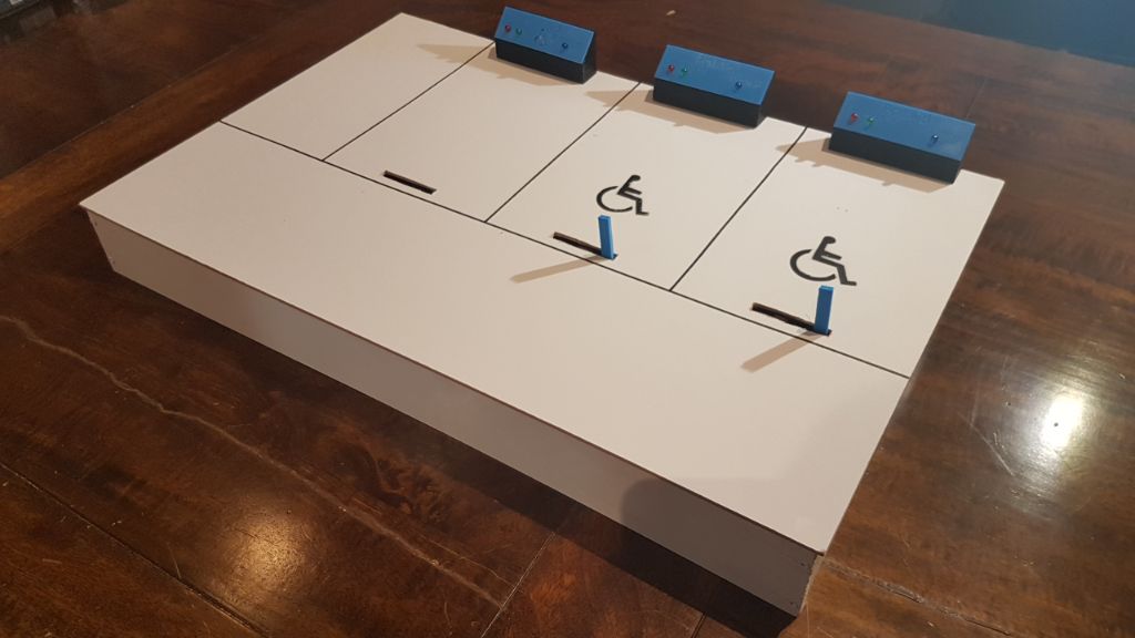
This gave me the scale for the rest of the demo. I used some MDF as the base with 3D printed control panels that would be used to indicate the state of each of the spaces (in real life these wouldn’t exist). I could also cut holes in the base to allow for the bollards to raise and lower. I designed it all in solidworks first.

Two of the spaces used the standard control plate which are permanent permit-only spaces. The Booked Now space lights up when the space is booked at this time and the Correctly Parked LEDs are green and red indicating if the car parked in the space is the one that booked it (green) or should not be parked there (red).

The third park is a variable space which only becomes permit-only when the first two spaces are taken. The centre disabled symbol indicates its status. It then behaves the same as the first spaces’ control plate.

The control plate stand was designed to be printed separately so there would be no overhangs (and therefore supports) required to 3D print.


The bollards were designed to slip over and be glued to the 9g servo motor arm.


Electronics Design
Here is the design for the electronics - each park would have its own ESP32 (NodeMCU) connected to the MFRC522 and LEDs for that space. The bollards were all attached to the fourth ESP32 and RFID reader which would raise/lower the correct bollard independently for stage 3.


In terms of the logic, here is the flowchart for spaces 1 and 2:

Also for space 3:

And finally for the bollards:

Final Presentation
I forgot to take a normal picture of the display so here’s a fantastic screenshot from my Snapchat story - I do apologise! It was a big hit as all the other Computer Science projects were on PC/Phones only.

Working Model
Here are a few videos of the stages working!