Building a Package Box for the Smart Home
As part of my Mechatronoics Engineering Final Year Project I developed a Package Box using RFID tags, a keypad and ESP32s that posties could securely deliver packages to that would interface with the central Smart Home Server.
Introduction
The Package Box is a secure box which will be situated out the front of the home near the front door. Packages may be placed in this box by the postie to keep them secure and out of the weather instead of being redirected to a post office. Home occupants will have electronic keys that open the box at any time, whereas a code may be used by the courier to allow single-access which can be put into the delivery instructions for each individual package.
This is the user flow diagram to better show how the system will be used.

Electrical Design
The initial design was to use an Arduino with added Wi-Fi connectivity via an ESP8266 ESP-01 module for the controller. However, during development, troubleshooting this configuration was taking up too much development time. A single NodeMCU board could not provide enough output pins on its own for all of the inputs so instead I used two NodeMCU (ESP-12E) boards.
A 16-key keypad for the keypad access was used to allow single-use access for the courier and with a MFRC522 RFID reader with either tags or cards that the home occupants may use to open the box.
A 12V lock-style solenoid was used as the locking mechanism. This solenoid has a resting state of locked and only becomes unlocked when energised. This is to keep the package box secure when there is no power as in a real system the package box would run off battery power.
I expanded on the user flow diagram to a more functional flowchart:

This is how I wired everything up:

And finally here is how the whole system interacts:

Mockups/Experiments
I hadn’t used the I2C interface for the screen before so I hooked up the screen (and eventually all of the electronics).
After I’d hooked up the relay I wanted to play around with the water valve as the same circuit could be used for both as they’re both 12V. The only thing is the valve relies on some pressure for the water to flow so yes, I was blowing on the other end of this pipe!
Hardware Design
I designed the module in solidworks first; it would be made out of 3mm MDF with a front panel that housed the electronics. In the real system the box would be bigger to accommodate bigger packages. The front panel would be 3D printed and made to fit all of the inputs and the screen.

While printing I had a few false starts with components not quite fitting and experimentation on which surface worked better - if it was printed face-side-up the results were much better.
Try, try again!


I made a mockup of the box using good ol’ cardboard just to make sure my idea for the control plate would work.
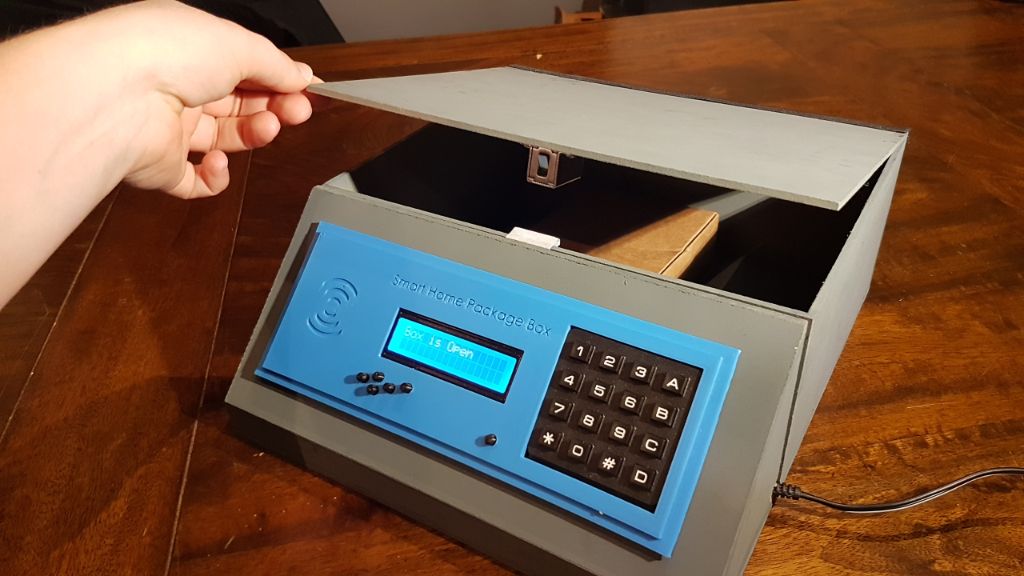
The fully fitted faceplate!

The underside was spaghetti - I still used the breadboard power supply and the wires were everywhere running to the keypad and screen (which both worked using the I2C interface) and the second NodeMCU for the RFID sensor.

Complete
Here is a badly screenshotted photo of our CapEx display that I took off my snapchat because I forgot to take a real photo!

And here is the final video showing the box in all its glory!
Software
This section is a bit more of a code-dump, so I put it down the bottom!
Main.ino
This is the code used in the main NodeMCU. It took some time to experiment with the I2C interfaces (the screen and the keypad). It just so happened that out of all the possible addresses, the devices I chose to use were the same address! But luckily the I2C converter I used for the keypad was configurable so I simply configured it for a different address. The two NodeMCUs work together in that they are powered from the same supply so when they are turned on, they both connect to WiFi then the main NodeMCU waits for the shared pin between the two to go low which signals the second NodeMCU is also ready.
#include <ESP8266WiFi.h>
#include <ESP8266HTTPClient.h>
#include <Adafruit_RGBLCDShield.h>
#include <Keypad_I2C.h>
#include <Keypad.h>
#include <Wire.h>
#include <ArduinoJson.h>

// Screen is at I2C address 0x20
// Keypad is at I2C address 0x21

// Setup Pins
#define DONE_PIN        D5          // Done setup flag from RFID NodeMCU
#define ACCESS_PIN      D6          // Access granted flag from FRID NodeMCU
#define LOCK_PIN        D7          // Pin to relay (solenoid)

// LOCK_SIGNAL states
#define SIGNAL_UNLOCKED LOW
#define SIGNAL_LOCKED   HIGH

// DONE states
#define DONE            LOW
#define NOT_DONE        HIGH

// Solenoid states
#define LOCK            HIGH
#define UNLOCK          LOW

// WiFi Setup
//String ipAddress = "192.168.1.14";
String ipAddress = "192.168.43.199";
String port = "3000";
// Initialise JSON parser
StaticJsonBuffer<1000> jsonBuffer;

// Screen Setup
Adafruit_RGBLCDShield lcd = Adafruit_RGBLCDShield();
#define WHITE 0x7       // For screen brightness

// Keypad Setup
#define KEY_ADDR 0x21   // Keypad I2C Address
#define CODE_LENGTH   8
const byte ROWS = 4; //four rows
const byte COLS = 4; //three columns
char keys[ROWS][COLS] =
{
  {'1','2','3','A'},
  {'4','5','6','B'},
  {'7','8','9','C'},
  {'*','0','#','D'}
};
// Keypad pinout (to I2C interface)
byte rowPins[ROWS] = {3, 2, 1, 0};
byte colPins[COLS] = {7, 6, 5, 4};
Keypad_I2C kpd( makeKeymap(keys), rowPins, colPins, ROWS, COLS, KEY_ADDR, PCF8574 );

// Variable Setup
int RFID_signal = SIGNAL_LOCKED;
int readySignal = NOT_DONE;
bool enteringKeycode = false;
char keyCode[CODE_LENGTH];
int codeIndex = 0;

void findWiFi();
void connectToWifi(char*, char*);
void sendHTTPPost(char*);

void setup() {
  // Set pins as input/output
  pinMode(ACCESS_PIN, INPUT_PULLUP);
  pinMode(DONE_PIN, INPUT_PULLUP);
  pinMode(LOCK_PIN, OUTPUT);

  // Initialise pins
  digitalWrite(LOCK_PIN, LOCK);

  // Initialise keypad
  kpd.begin( makeKeymap(keys) );

  // Setup serial output
  Serial.begin(115200);

  // Set up LCD:
  lcd.begin(16, 2);
  lcd.setBacklight(WHITE);
  lcd.print("Starting up...");
  Serial.println("Starting up...");

  // Set up WiFi
  // Set WiFi to station mode and disconnect from an AP if it was previously connected
  WiFi.mode(WIFI_STA);
  WiFi.disconnect();
  delay(2000);
  findWiFi();

  // Loop until the other NodeMCU is ready
  while(digitalRead(DONE_PIN) == NOT_DONE)
  {
    delay(200);
  }

  lcd.clear();
  lcd.print("Ready!");
  Serial.print("Ready!");
}

void loop() {
  // Lock box again
  digitalWrite(LOCK_PIN, LOCK);

  // Get any keypress or RFID input
  char key = kpd.getKey();
  RFID_signal = digitalRead(ACCESS_PIN);

  if(WiFi.status() == WL_CONNECTED)
  {

    // Use any keypress or RFID input
    if (key){
      Serial.println(key);
      if (!enteringKeycode)
      {
        lcd.clear();
        lcd.setCursor(0, 0);
        lcd.print("Entering Code:");
        enteringKeycode = true;
        codeIndex = 0;
      }
      if (key == '*')
      {
        lcd.clear();
        lcd.print("Ready!");
        Serial.print("Ready!");
        memset(keyCode, 0, sizeof keyCode);
        enteringKeycode = false;
      }
      else if (key == '#')
      {
        lcd.setCursor(0, 0);
        lcd.print("SENDING CODE...");
        sendHTTPPost(keyCode);
        enteringKeycode = false;
        memset(keyCode, 0, sizeof keyCode);
        //delay(3000);
        lcd.clear();
        lcd.print("Ready!");
      }
      else if (codeIndex <= CODE_LENGTH)
      {
        lcd.setCursor(codeIndex, 1);
        lcd.print(key);
        keyCode[codeIndex] = key;
        codeIndex++;
      }
    }
    else if (RFID_signal == SIGNAL_UNLOCKED)
    {
      lcd.clear();
      lcd.setCursor(0,0);
      digitalWrite(LOCK_PIN, UNLOCK);
      lcd.print("Box is Open");
      Serial.println("Box is Open");
      delay(5000);
      lcd.clear();
      lcd.print("Ready!");
    }

    uint8_t buttons = lcd.readButtons();

    if (buttons) {
      lcd.clear();
      lcd.setCursor(0,0);
      if (buttons & BUTTON_UP) {
        lcd.print("UP ");
        digitalWrite(LOCK_PIN, HIGH);
      }
      if (buttons & BUTTON_DOWN) {
        lcd.print("DOWN ");
        digitalWrite(LOCK_PIN, LOW);
      }
      if (buttons & BUTTON_LEFT) {
        lcd.print("LEFT ");
      }
      if (buttons & BUTTON_RIGHT) {
        lcd.print("RIGHT ");
      }
      if (buttons & BUTTON_SELECT) {
        lcd.print("SELECT ");
      }
    }
  }
  else
  {
    lcd.clear();
    lcd.print("Reconnecting...");
    findWiFi();
    lcd.clear();
    lcd.print("Ready!");
  }
}

/*
 * Finds one of the WiFi networks defined within this function and connects to it.
 */
void findWiFi() {

  // Variables
  char* ssid;
  char* password;

  Serial.println("scan start");
  int n = WiFi.scanNetworks();
  if (n == 0)
    Serial.println("no networks found");
  else
  {
    for (int i = 0; i < n; ++i)
    {
      if (WiFi.SSID(i).equals("WiFi1"))
      {
        Serial.println("Found WiFi1");
        ssid = "WiFi1";
        password = "thisisapassword";
        connectToWifi(ssid, password);
      }
      else if (WiFi.SSID(i).equals("TwulzPhone"))
      {
        Serial.println("Found TwulzPhone");
        ssid = "TwulzPhone";
        password = "yeahnottellingyou";
        connectToWifi(ssid, password);
      }
    }
  }
}

/*
 * Connects to the wifi given by the arguments.
 */
void connectToWifi(char* ssid, char* password) {
  WiFi.begin(ssid, password);             // Connect to the network
  Serial.print("Connecting to ");
  Serial.print(ssid); Serial.println(" ...");

  int i = 0;
  while (WiFi.status() != WL_CONNECTED) { // Wait for the Wi-Fi to connect
    delay(1000);
    Serial.print(++i); Serial.print(' ');
  }

  Serial.println('\n');
  Serial.println("Connection established!");
  Serial.print("IP address:\t");
  Serial.println(WiFi.localIP());         // Send the IP address of the ESP8266 to the computer
  digitalWrite(DONE_PIN, DONE);                  // Tell the other NodeMCU this is ready.
}

/*
 * Sends the accessCode to the server via JSON message and turns on the appropriate
 * LED depending on the response.
*/
void sendHTTPPost(char* code)
{
    HTTPClient http;
    String payload;
    int httpCode;

    // POST sample:
    Serial.println("POST:");
    http.begin("http://" + ipAddress + ":" + port + "/packageCode/");
    http.addHeader("Content-Type", "application/json");
    String postReq = (String)"{\"keyCode\": \"" + code + (String)"\"}";
    Serial.println(postReq);
    httpCode = http.POST(postReq);
    payload = http.getString();
    Serial.println("httpCode:");
    Serial.println(httpCode);
    Serial.println("payload:");
    Serial.println(payload);
    JsonObject& root = jsonBuffer.parseObject(payload);
    if (!root.success())
    {
      Serial.println("parseObject() failed");
    }
    else
    {
      String response = root["response"];
      Serial.println(response);
      if(response.equals("Access Granted"))
      {
        lcd.clear();
        lcd.setCursor(0,0);
        digitalWrite(LOCK_PIN, UNLOCK);
        lcd.print("Box is Open");
        Serial.println("Box is Open");
        delay(5000);
        lcd.clear();
        lcd.print("Ready!");
      }
      else
      {
        lcd.clear();
        lcd.print("Keycode Invalid");
        delay(5000);
      }
    }
    http.end();
}
RFID NodeMCU
This program searches for and connects to one of the given WiFi networks (whichever is found). Once found it searches for a tag on the RFID reader, when one is found it sends this data as a JSON code over HTTP Post request. If the response has “Access granted” this is displayed and the box is opened, if not, the response “Access denied” is displayed and the box remains locked.
/*
 * HTTP_Req_RFID
 *
 *
 * Issues:
 * JSON parser runs out of memory? or otherwise stops working after 5-6 parses.
 * IP address is currently hard-coded.
*/
#include <ESP8266WiFi.h>
#include <ESP8266HTTPClient.h>
#include <SPI.h>
#include <MFRC522.h>
#include <ArduinoJson.h>

// Initialise for RFID (MFRC522)
#define RST_PIN         D3
#define SS_PIN          D4
MFRC522 mfrc522(SS_PIN, RST_PIN);

// Communication Pins (to other NodeMCU)
#define DONE_PIN        D1
#define ACCESS_PIN      D2

// LOCK states
#define SIGNAL_UNLOCKED        LOW
#define SIGNAL_LOCKED          HIGH

// DONE states
#define DONE            LOW
#define NOT_DONE        HIGH

// Initialise for WiFi Connection
//String ipAddress = "192.168.1.14";
String ipAddress = "192.168.43.199";
String port = "3000";

// Initialise JSON parser
StaticJsonBuffer<1000> jsonBuffer;

// Function declarations
void findWiFi();
void connectToWifi(char* ssid, char* password);
void dump_byte_array();
String RfidScan();
String getRFIDString(byte *buffer, byte bufferSize);
void sendHTTPPost();

// Variables
String accessCode = "UNDEF";

void setup() {
  //LED
  pinMode(ACCESS_PIN, OUTPUT);
  pinMode(DONE_PIN, OUTPUT);
  digitalWrite(DONE_PIN, NOT_DONE);    // Indicate that WiFi isn't connected yet
  digitalWrite(ACCESS_PIN, SIGNAL_LOCKED);
  Serial.begin(115200);
  delay(2000);
  // Set up the MFRC522
  SPI.begin();
  mfrc522.PCD_Init();
  // Set WiFi to station mode and disconnect from an AP if it was previously connected
  WiFi.mode(WIFI_STA);
  WiFi.disconnect();
  delay(2000);
  Serial.println("Setup done");

  findWiFi();
}

void loop() {
  digitalWrite(ACCESS_PIN, SIGNAL_LOCKED);
  // HTTP Request code
  if(WiFi.status() == WL_CONNECTED)
  {
    // Get the RFID code
    accessCode = RfidScan();
    if (!accessCode.equals("UNDEF"))
    {
        Serial.println("Code: -" + accessCode + "-");
        sendHTTPPost();
    }
  }
  else
  {
    Serial.println("Error: No WiFi connection");
    findWiFi();
  }
}

/*
 * Sends the accessCode to the server via JSON message and turns on the appropriate
 * LED depending on the response.
*/
void sendHTTPPost()
{
    HTTPClient http;
    String payload;
    int httpCode;

    // POST sample:
    Serial.println("POST:");
    http.begin("http://" + ipAddress + ":" + port + "/access/");
    http.addHeader("Content-Type", "application/json");
    String postReq = (String)"{\"fobCardCode\": \"" + accessCode + (String)"\"}";
    Serial.println(postReq);
    httpCode = http.POST(postReq);
    payload = http.getString();
    Serial.println("httpCode:");
    Serial.println(httpCode);
    Serial.println("payload:");
    Serial.println(payload);
    JsonObject& root = jsonBuffer.parseObject(payload);
    if (!root.success())
    {
      Serial.println("parseObject() failed");
    }
    else
    {
      String response = root["response"];
      Serial.println(response);
      if(response.equals("Access Granted"))
      {
        digitalWrite(ACCESS_PIN, SIGNAL_UNLOCKED);
      }
      else
      {
        digitalWrite(ACCESS_PIN, SIGNAL_LOCKED);
      }
      delay(3000);
    }
    http.end();
}

/*
 * Finds one of the WiFi networks defined within this function and connects to it.
 */
void findWiFi() {

  // Variables
  char* ssid;
  char* password;

  Serial.println("scan start");
  int n = WiFi.scanNetworks();
  if (n == 0)
    Serial.println("no networks found");
  else
  {
    for (int i = 0; i < n; ++i)
    {
      if (WiFi.SSID(i).equals("WiFi1"))
      {
        Serial.println("Found WiFi1");
        ssid = "WiFi1";
        password = "thisisapassword";
        connectToWifi(ssid, password);
      }
      else if (WiFi.SSID(i).equals("TwulzPhone"))
      {
        Serial.println("Found TwulzPhone");
        ssid = "TwulzPhone";
        password = "yeahnottellingyou";
        connectToWifi(ssid, password);
      }
    }
  }
}

/*
 * Connects to the wifi given by the arguments.
 */
void connectToWifi(char* ssid, char* password) {
  WiFi.begin(ssid, password);             // Connect to the network
  Serial.print("Connecting to ");
  Serial.print(ssid); Serial.println(" ...");

  int i = 0;
  while (WiFi.status() != WL_CONNECTED) { // Wait for the Wi-Fi to connect
    delay(1000);
    Serial.print(++i); Serial.print(' ');
  }

  Serial.println('\n');
  Serial.println("Connection established!");
  Serial.print("IP address:\t");
  Serial.println(WiFi.localIP());         // Send the IP address of the ESP8266 to the computer
  digitalWrite(DONE_PIN, DONE);                  // Tell the other NodeMCU this is ready.
}

/*
 * (Not used currently) prints out the RFID code from the byte array from the sensor.
 */
void dump_byte_array(byte *buffer, byte bufferSize)
{
  for (byte i = 0; i < bufferSize; i++)
  {
    Serial.print(buffer[i] < 0x10 ? " 0" : " ");
    Serial.print(buffer[i], HEX);
  }
  Serial.print("\n");
}

/*
 * Searches RFID sensor for a tag or card and returns a String of this code.
 */
String RfidScan()
{
  if ( ! mfrc522.PICC_IsNewCardPresent())
  {
    return "UNDEF";
  }

  if ( ! mfrc522.PICC_ReadCardSerial())
  {
    return "UNDEF";
  }
  //dump_byte_array(mfrc522.uid.uidByte, mfrc522.uid.size);
  return getRFIDString(mfrc522.uid.uidByte, mfrc522.uid.size);
}

/*
 * Takes the byte array returned by the RFID sensor and returns a String version of it.
 */
String getRFIDString(byte *buffer, byte bufferSize)
{
  String strID = "";
  for (byte i = 0; i < bufferSize; i++) {
    strID +=
      (buffer[i] < 0x10 ? "0" : "") +
      String(buffer[i], HEX);
      //(i != 3 ? " " : "");
  }
  strID.toUpperCase();
  return strID;
}