Building a Pick-and-Place Robot using MyRIO and LabView
I made a pick-and-place robot as a project at university which was programmed using the LabView program running on a myRIO controller.
Background
This project was meant to be a four-person project where we were required to build a pick-and-place robot that could move as many “blocks” as possible between the pickup and dropoff points in a timed competition. I ended up doing almost the entire project myself - 2 of the other groupmates worked on the the mechanical design of the arm only and the third member did nothing at all. SO I’m a little bitter now about this project but I’ve dubbed him my very own ‘Shitty Robot’ and I’m writing this post after-the-fact so please forgive the gaps!

The above picture shows the first drop point that was designed but the cubes would often get stuck in the opening as they dropped.

So I mocked up another design with a bigger hole to see if the problem would still persist at this size.


I then glued a new droppoint using the offcuts from the rest of the robot - no extra laser cutting required!

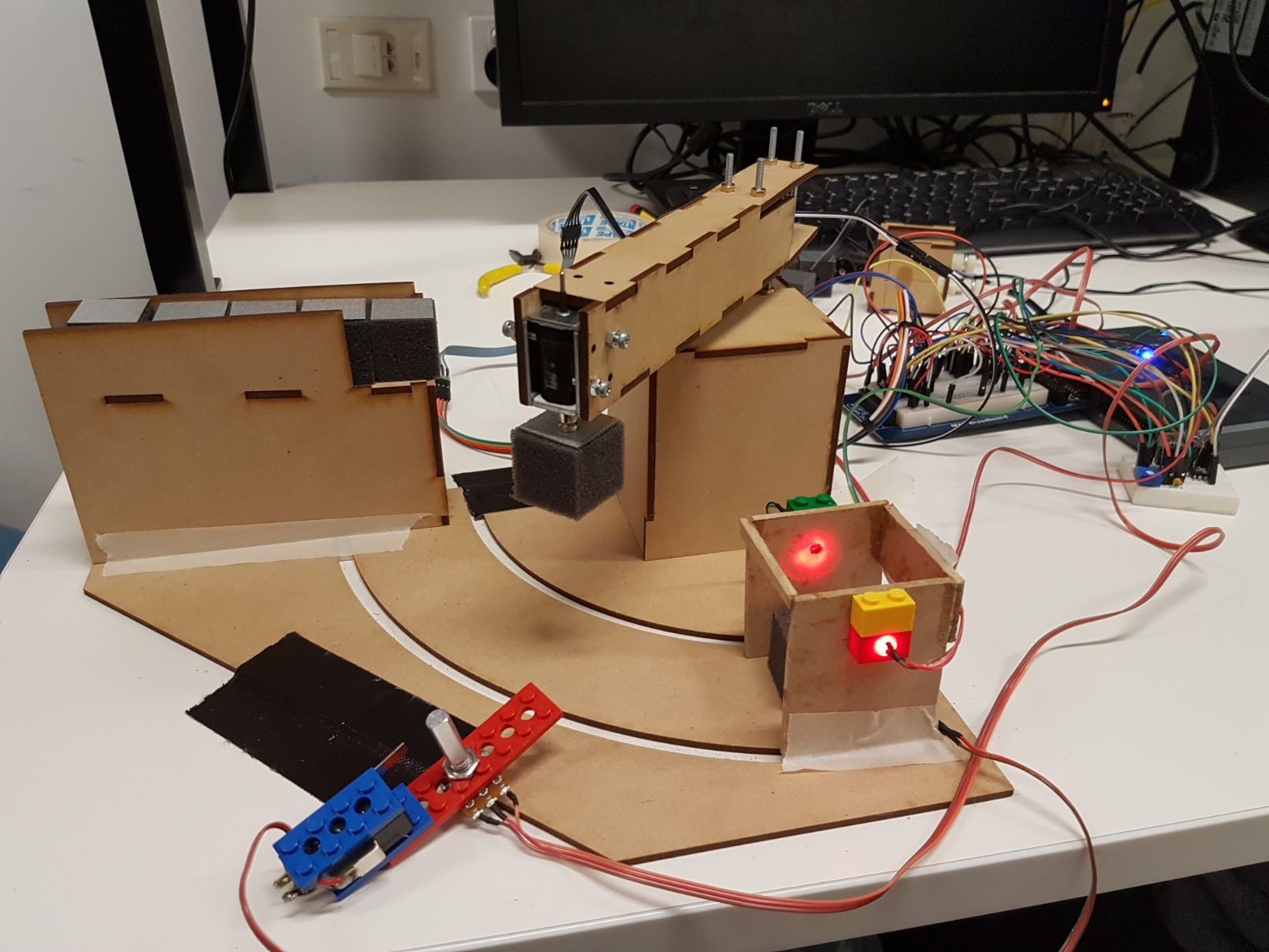
Here is the completed robot during the testing phase.

There was some experimentation with the magnet used to pick up the cubes to reliably pick it up from the feeder and drop it off at the box.
Please ignore the mess of wires on the breadboard!


Here is the final LabView program used for the robot, note this is the “automatic” program, some notes on its operation:
-
A square wave with a given frequency acts as the set point input.
-
The positions the arm reaches are determined by the offset and amplitude of this square wave set on the front panel.
-
The PID controller uses PID values as set on the front panel. For this application, it was found that only proportional control was required in order to operate reliably however the value of this control varies between the values 1-2.5 with the charge level of the battery so the option to recalibrate this figure from the front panel is well worthwhile.
-
The sign of the output of the PID is used to determine the motor direction and its absolute value is used as the duty cycle PWM. The minimum and maximum values of this output are also able to be set from the front panel but experimental results show that a range of -0.3 to 0.3 is ideal.
-
The electromagnet is engaged (with duty cycle 0.5) when the set point reaches the smaller set point value which automatically adjusts when the set points are changed. It similarly disengages to drop the block off at the larger set point value.
-
The front panel displays the current position of the motor as a graph and the set point on a gauge.


I thought I’d just throw in the small program I used for manual operation to move the arm and pick up the cube using buttons on the front panel. This was mainly useful to get the boundary values to use.

Here is a zoom in on the counter part of the program - we had to be able to accurately count how many cubes were delivered to the delivery point for them to be recorded for the competition. When the beam is broken (contained in the lego bricks on the dropoff point above) it records one block.

This is the program used to gather data for the system identification; I was trying to get the transfer function of the system so I could calculate theoretical PID values, but in the end the error was too high - I was getting much better results tuning the PID values manually.

I used a motion tracking software called tracker to track the motion of the arm doing full 360 motion but as I said, the manual results were better!
![]()
Finally this is the full schematic of the system. Note the filter added between the output of the op amp into the DC motor (used in the robotic arm).

I’m really kicking myself, I don’t know what happened to my final video showing the complete system - I did spend the majority of the time trying to reload the damn thing! The only video of the robot mostly working is the one without the fixed dropoff point.
For the final presentation it still occasionally missed the blocks from the feeder and/or dropped it on the way to the dropoff point but really the weakest link was our ability to unload from the dropoff point and reload the cubes over at the feeder - we couldn’t keep up!